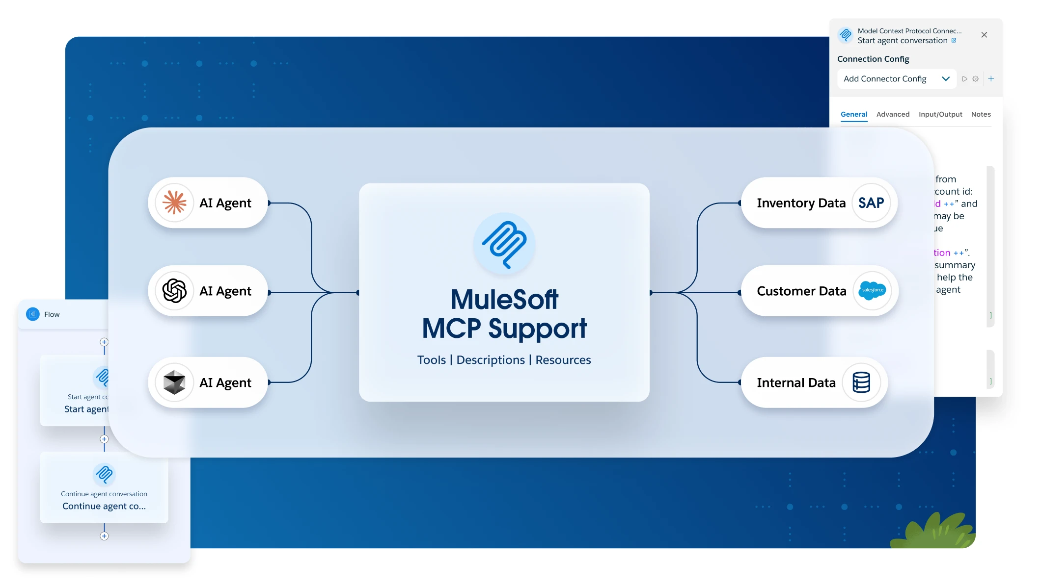
The new deployment model is extremely useful for a number scenarios. For example if you have an application that produces purchase orders that should be transformed to different formats depending on the supplier identifier within the message payload as shown in figure 1.
Fig.1 Example Use Case
The Mule 2 way to solve this would be to create three flows within the same Mule application as shown in figure 2, one flow does the content based routing and routes the message to one of the two supplier specific flows. Consider the scenario that after deployment one of the suppliers would like to change their format in some way requiring the transformation to be updated. Since all three Mule flows are contained within the same application all of the three flows will need to be redeployed even if the change is only relevant to one of them. This might be manageable for two or three suppliers but as your solution grows and you need to connect to a large number of suppliers the redeploys might become a problem.
Fig.2 Single Application Fig.3 Multiple Applications
Splitting the three flows into three different Mule applications, as shown in figure 3, allows changes to an individual supplier flow separately without affecting the message exchange with another supplier. Even if the limited downtime during the deploy may not be considered a problem it limits the risk of the deployment. Figure 4 illustrates a possible setup for the use case described earlier where an application publishes a message to a routing component that based on the content of that message routs it to the appropriate supplier specific flow via a JMS queue.
Fig.4 Deployment Model: Router – Supplier
If one of the Supplier flows consumes a lot of resources or new SLA requirements are introduced, that specific part of the solution can be moved to a dedicated server without having to update the code in any way. This task could easily be managed by an operations team without having to involve any developer in the process.
Figure 5 illustrates how the “Supplier B Flow” have been separated out to another server.
Fig.5 Deployment Model: Router – Supplier A – Supplier B
To summarize, when designing and structuring Mule applications, it’s important to consider the frequency with which parts of the solution will need to change and grow. Failure to do so may lead to monolithic applications that are extremely hard to manage and troubleshoot. The benefit of partitioning flows and services that may change or grow gives much more deployment flexibility should your architecture need to change to result in increased load or a change in requirements.


